SOK Battery BMS Upgrade
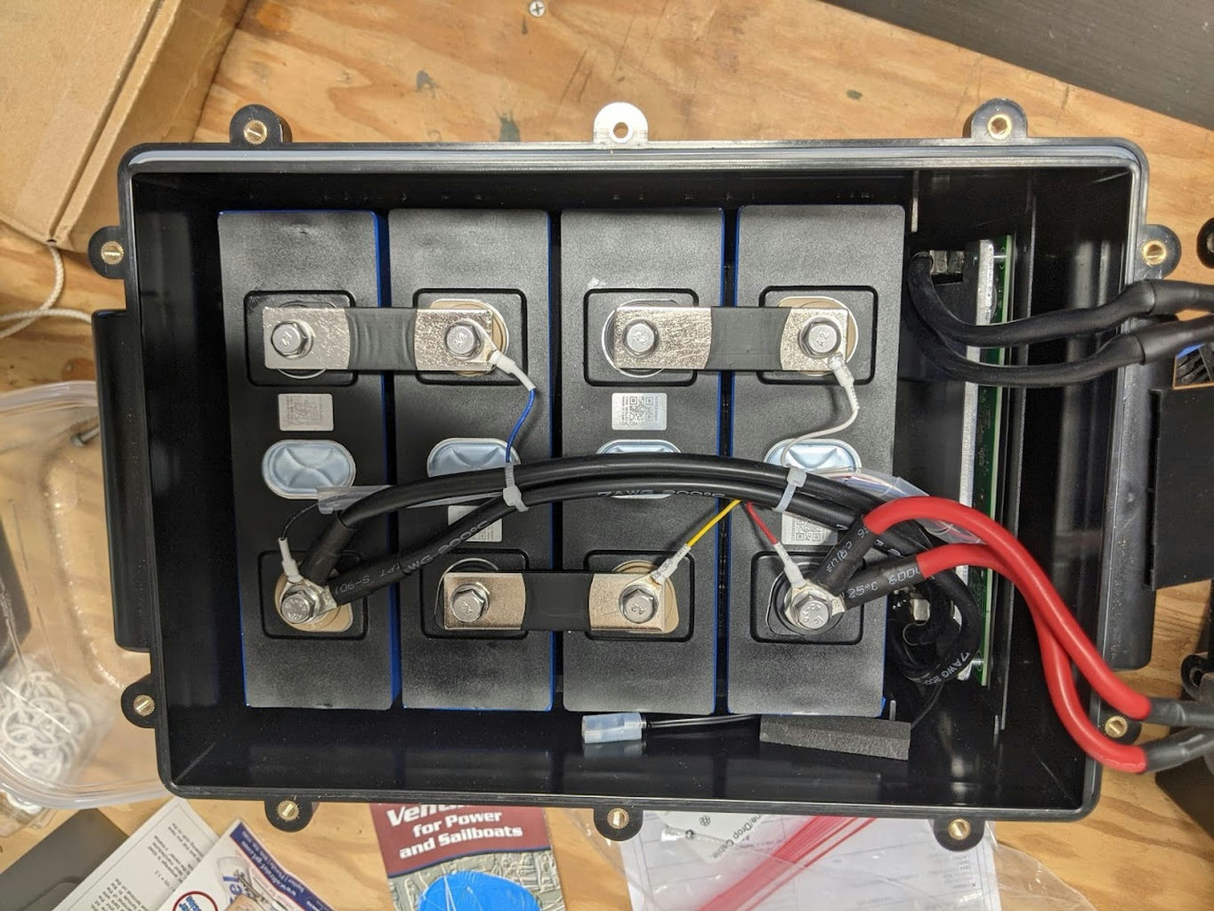
Here's the write-up I wished I could find when I set out to upgrade my 206Ah SOK batteries to use the Bluetooth-enabled BMS.
I love the idea of SOK LiFePO4 batteries: use automotive grade prismatic cells in a resealable plastic case and permit DIY repairs and upgrades. There's an active user community on (ugh) Facebook, but not a wealth of documentation from manufacturer or the community. My chance to pay it forward.
But this is not that authoritative guide, no matter how certain it may sound. Here are the mistakes I know I made:
- I used too much torque on the aluminum (or whatever light alloy) terminals of the prismatic cells. I was aiming for 10 N M, but I'm new with the torque wrench and it definitely felt too tight so I stopped short of that on most of the bolts. Nothing felt like it actually let go, however, so I'm just going to leave things as they are, so this will be something to be nervous about when I do the first full load test: I will be monitoring the temperature of all the cell terminals (with my trusty IR thermometer).
For you, dear reader, see if you can find an actual manufacturer's spec and perhaps you'll already have experience with and confidence in your torque wrench. - I stripped one of the phillips head bolts used to attach a power cable to the BMS circuit board. Then I found a bigger screwdriver with a head that fit correctly and got the rest of the bolts out OK. SOK provides new bolts with the new BMS, so no harm, no foul.
- I wasted time taking apart more than I needed to, and, though I learned a lot as I proceeded, I don't have as much confidence in the first battery as the second.
And maybe some reader will kindly point out additional mistakes I don't know about yet.
Process
The upgrade is really quite straightforward, no EE degree required, though prior experience with a torque wrench would have been handy.
Obligitory safety warning
These batteries concentrate a lot of energy in a small package, and are cleverly designed to discharge that energy very rapidly, even from a partially discharged state (as they are shipped).
12 VDC won't electrocute you directly, but 200 A through a tool shorted across the terminals of any one of the cells or the whole battery can burn you or pepper you with rapidly accelerated bits of perhaps molten metal (think rail gun). So take your time, open the most negative return path first and reconnect it last, insulate your tools and watch out for thick cables with a tendency to slowly creep back into contact with the terminal you just disconnected them from.
Tools you'll need
- 10 mm socket -- For the M10 bolts on the terminals of the prismatic cells.
- Torque wrench set for about 7 N M (about 88 in lbs). Confirmation on this value still pending from SOK.
(NOTE: originally 10 N M, and the wisdom of the internet is that's too tight for M10 s/s bolt into aluminum.)- Allen head wrench -- for the plastic case bolts
- #3 (?) Phillips head screwdriver
Used to unscrew the power cable bolts from the posts on the BMS. My standard phillips screwdriver stripped out one of these, but the bigger screwdriver was a perfect fit. - Plastic (nonconductive) putty knife
This made it easy to get the BMS mounting tray free to slide out of the case without worrying about shorting or breaking anything. - Dielectric grease
I was thinking I'd protect the various internal bolts from salt corrosion with this non-conductive grease that is rated for battery terminals on land or sea, but SOK advised against it and in fact the battery didn't have any as it came from the factory. So I didn't use this on any internal connection, but did use it on the external bolts around the case and will use it on all the exposed 12V connections on the boat.
Open the case
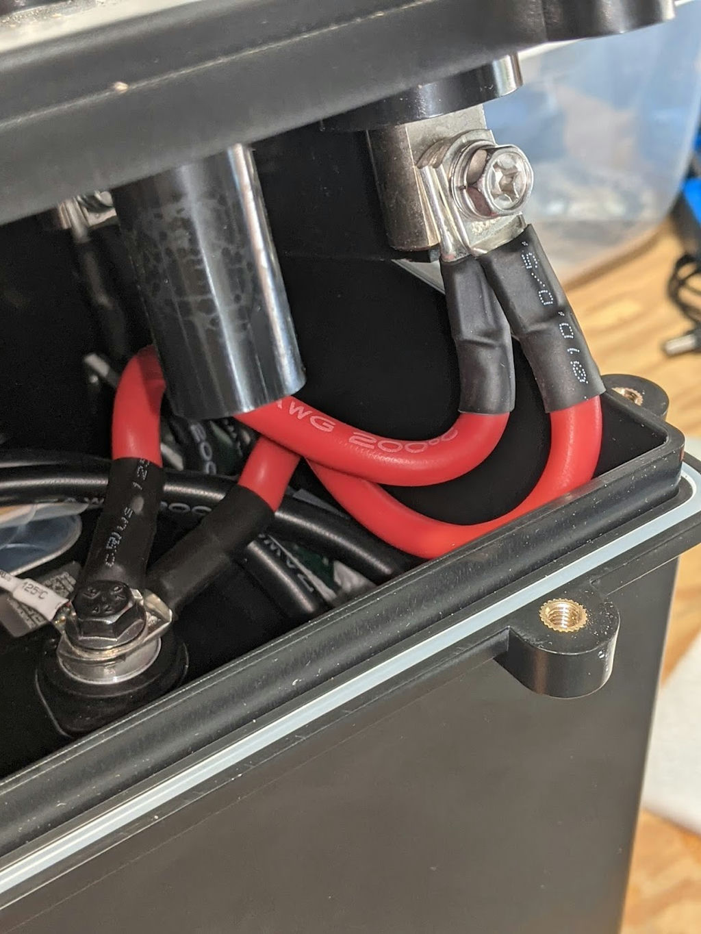
- Remove the bolts around the cover.
- Gently open the case. You'll find the power connections under the terminals are stiff, short and kind of jammed together. The negative and positive cables cross over each other with very little spacing.
- Perhaps take some pictures to remind yourself of how to pack them back in.
Disconnect power cables and balance harness from battery
-
For safety, remove the negative and then the positive main power cables from the internal cells first.
That reduces the number of ways you can melt a screwdriver.As you do this, get a feel for how tight the bolts were installed at the factory, and set your torque wrench to match. Proper torque is in the range 5-7 N M, to avoid stripping the (aluminum?) cell terminals, but it doesn't feel all that tight.
-
I continued by removing the balance cable harness as well. You could probably complete this project leaving it attached, but I felt safer working on the battery without having loose cables laying on the cells. YMMV.

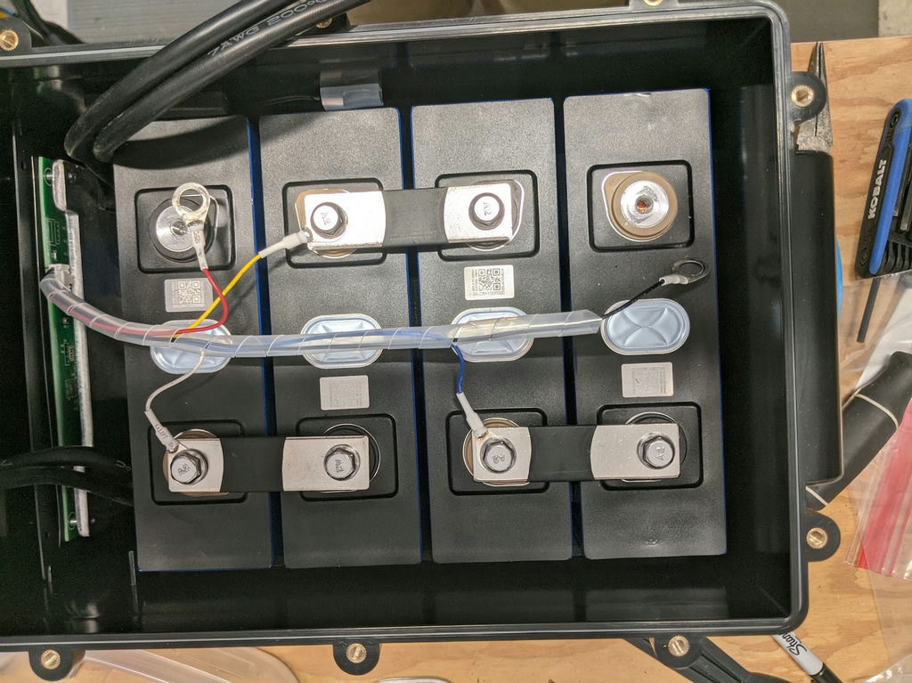
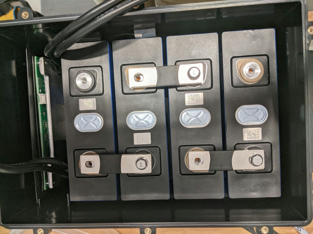
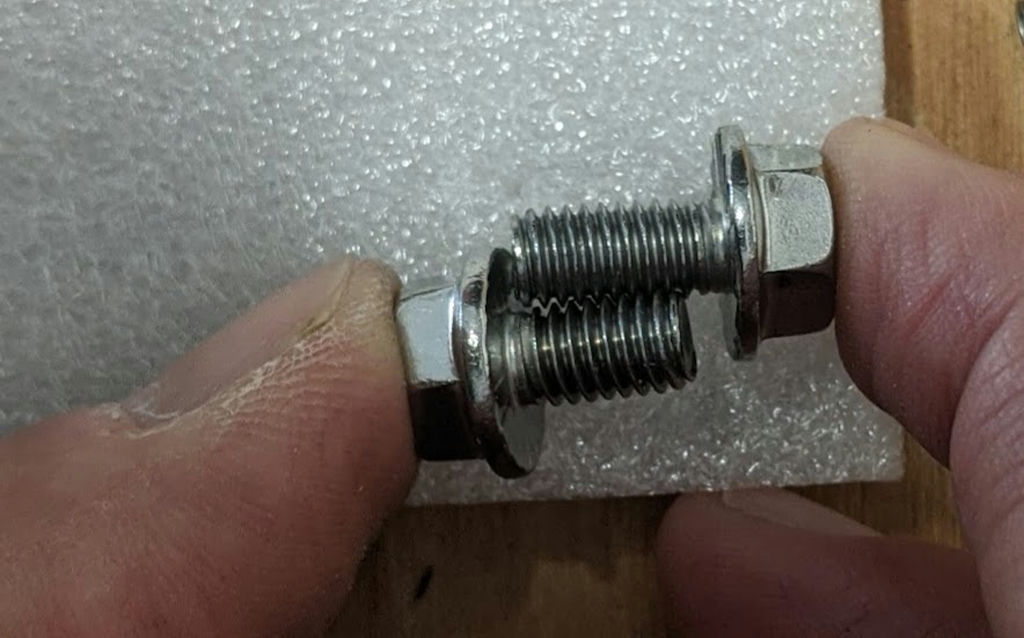
If you do remove the balance harness, note there are 2 lengths of bolts on the cell terminals, and the bolts holding just the balancing lead and bus bar are shorter than the ones holding the main power cables + balancing lead + bus bar. Be sure to re-install them that way!
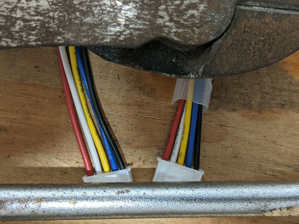
SOK ships a new balance harness with the BMS, but I reused the existing one since it is already trimmed to fit. I checked, it does have the same pin-out and connector as the old.
Remove the old BMS assembly and disassemble from the tray
When I first looked into the case, I thought the BMS mounting tray was fastened down and might be tricky to remove. But it's just a (nice, snug) slide-in fit secured by closed-foam pads on both sides.
- Unclip the balance harness connector from the top of the BMS.
- Unclip the temperature sensor from the soft plastic holder stuck to the inside of the case. Carefully work the wire around the cells till it's free to come out with the BMS.
Realistically, you could just clip the wire because the new BMS comes with its own sensor. - Grasp the metal mounting tray firmly and wiggle the BMS assembly up out of the case. I used my plastic putty knife between the stack of black foam and the first cell to help (this stack is adhered to the BMS).
- Remove the metal mounting tray and plastic separator sheet from the old BMS PCB. Lay the blue closed cell cushioning spacer on the separator sheet and put that to one side where it won't accumulate bench debris. Retain the 4 little bolts (though SOK ships replacements with the new BMS)
- Remove the stack of neoprene spacers from the old BMS heat sink. They are stuck on with light adhesive, but I got a clean parting using my trusty plastic putty knife.
Leave BMS attached to the negative terminal on the case for now.
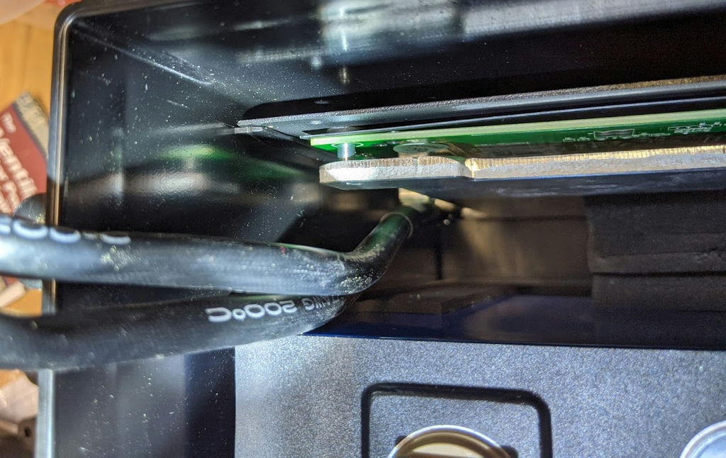
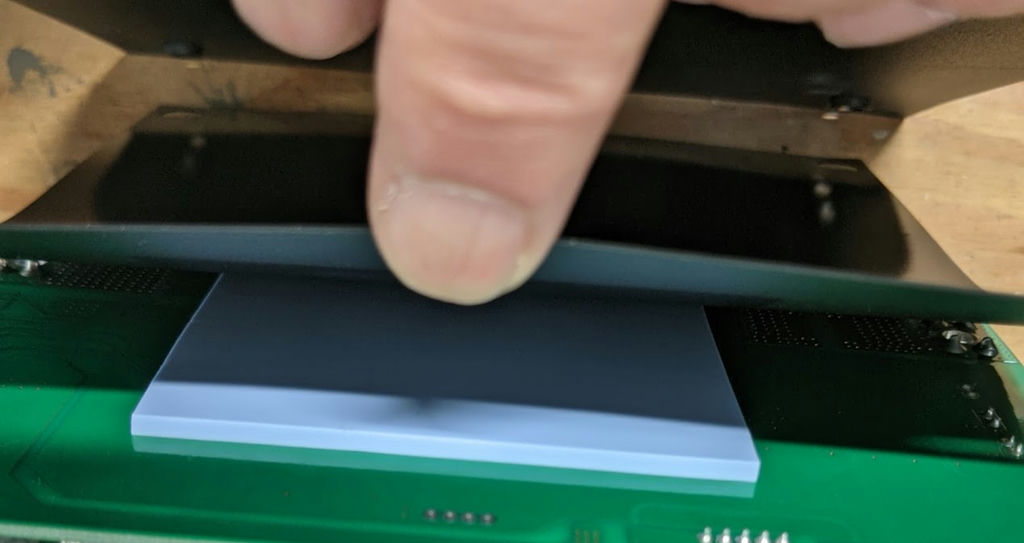
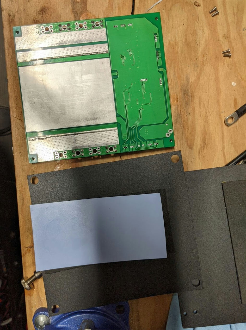
Eagle eyed readers will note that the last picture shows the cables already removed (next step). But taking the BMS off now makes the next step easier.
Remove the power cables from the old BMS
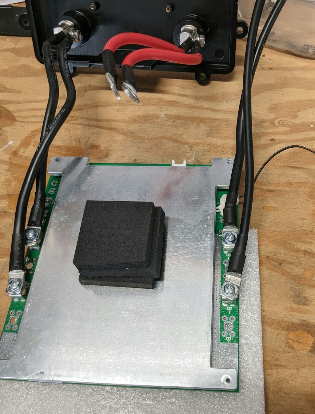
It's simple: you want to unscrew all the cables from the old BMS and reconnect them to the same post on the new BMS, which fortunately is 100% plug-compatible. Although the cables going, e.g, to the negative external battery post are electrically equivalent, physically each cable is a different length, so you should label which individual cable came from each BMS post. And youxxxxxxxxxxxxxxx whichElectrically speaking, the 2 cables connected to the negative external post are interchangable and could be connected to either the P- or C- post on the BMS. Likewise the 2 cables connected to the negative terminal of the bottom prismatic cell and the BMS B- posts. However (safety warning), the P-/C- posts are electrically different from the B-/B- posts. Crossing sides will absolutely void the manufacturer's warranty and ruin your day. Phy
- Lay the PCB on your bench with the foil side of the PCB down, and protected from the bench with, e.g the square of closed cell packing material the BMS was shipped with. You're probably going to exert a fair amount of downward pressure getting the cables off and you do not want to strain or crack the PCB.
- Using a phillips head screwdriver with a nice snug fit to the keeper bolt heads, remove all 4 bolts. As you do, label each cable with the post it came from, so you are certain which is which when you reassemble things.
Install the power cables on new BMS
Hands on the new BMS!
I don't have a picture for this, but the steps are the reverse of the previous steps
- Center the new BMS on the packing material pad you used above.
- Using the new bolts that came with the BMS and the same snug-fitting screwdriver, and once again checking that you're connecting each cable to the correct post, bolt the connector lugs to the BMS posts and snug them down "firmly".
Install the new BMS on the mounting tray
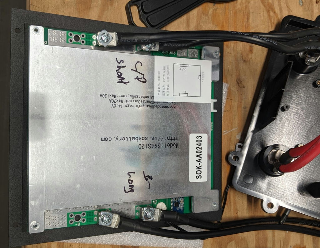
This is a bit tricky: you want the plastic separator getting pinched between the mounting tray standoffs and the BMS PCB, . If you squeeze the assembly together before the holes clear the standoffs, the blue cushion closed cell pad will grip and prevent you from getting everything to line up. Disassemble and try again.
- Remove the 4 little bolts from the PCB side of the new BMS.
- With the BMS laying on the heat sink and the PCB side facing up, note the big foil rectangle on the PCB (ground plane?).
- Transfer the blue cushioning pad from the separator sheet to the big rectangle on the PCB. Try to get it to cover the rectangle and align nicely with the edge of the PCB.
- Resettle the plastic separator sheet on the mounting tray, with all 4 holes laying clear of the standoffs.
- Stand the mounting tray up vertical and feed the top 2 bolts through to the PCB, leaving them loose, followed by the bottom 2 bolts, likewise loose.
- Make one last check that the plastic separator holes are clear of all 4 standoffs, then tighten all 4 bolts.
Install the BMS assembly in the battery
- Attach the stack of neoprene spacers to the center of the heat sink on the new BMS. Exact location is not critical.
- Stand the BMS tray on edge with the small white socket for balancing harness on top. Power cables to external post will be to the left, battery temperature sensor to the right.
- Slide the assembly into the battery case. Note the lip in the case that supports the metal tray: the tray slides down the side of the lip away from the cells. Push the tray all the way down to the bottom of the case. The BMS should be a snug fit, held in place by the neoprene spacers between the cells and the edge of the case.
- Run the temp sensor wire around the corner of the prismatic cell, under the small strip of neoprene and tuck the sensor end into the soft rubber sensor holder stuck to the side of the case. You may have to move the sensor holder so the sensor stays put.